MC6847 external character ROM

At one point I decided to do a remake of the “Lowerkit” for the CoCo 2.

This external character set board for the 6847 will allow for fonts other than the built in set in the VDU to be used.  A character set for the 6847 is 2048 bytes (2k), representing 128 ASCII character codes (0 – 127).

This version uses a 16k rom chip, providing room for 8 character sets selectable in banks by dip switch.

This version was one of my earlier CoCo projects, and used standard TTL logic.  Though a bit bulky, it worked just fine.  I actually still have this one installed in a Tano Dragon, where it has plenty of room.

20141220_213812
MC6847 external character ROM prototype, top
20141220_213910
MC6847 external character ROM prototype, bottom
20150116_182934 (1)
Installed in a CoCo2
20150116_150022
External ROM in action
20150116_181545
New character set with boot screen

Compared to the built in ROM

The next step will be to explore moving the logic into a cpld in order to get
the board size down, and then creating final board layouts for the various
CoCo1 and CoCo2 models.

I’ve put together an excel spreadsheet that aids in the creation of fonts for
the MC6847 that can be found at the end of this page. It lets me design a font in a visual manner, and generates the hex code for the rom.

The next board

Experimenting from the MC6847 External ROM board I put together earlier, I then built this version in part to learn about using CPLDs.

I built the earlier version using 7400 series logic, and thought migrating the design to CPLD would be a good learning exercise. I decided to use Xilinx chips, as I had already built a programmer for the PLCC version of the 9500xl family.

20150303_082550
REV 01 MC6847 External Character ROM using CPLDs

I split the logic over 2 CPLDs as I needed more pins than one would supply (without moving to SMD). The 9572xl holds the logic for rerouting addressing to the 27C256 EPROM and handles the associated selection lines to the MC6847. The 9536xl holds a 4 bit counter and flip-flop used to handle the row addressing on the EPROM.

Outputs from these CPLDs can drive TTL inputs, and can also be configured as open-collector outputs, which I did try out, using some add-on pull-ups under the board. Useful for driving TTL with a bit more voltage than the standard output buffer allows.

20150303_220213
Output using the External ROM

As you can see, it works pretty well. I did learn quite a bit about designing the internal logic for these CPLDs using the Xilinx ISE suite.

For the next revision I’ll adapt the design to SMD, using the VQF-64 version of the 9572xl to hold all the logic, making for a more compact board.

20150303_082444 (1)
Installed on a CoCo2 motherboard

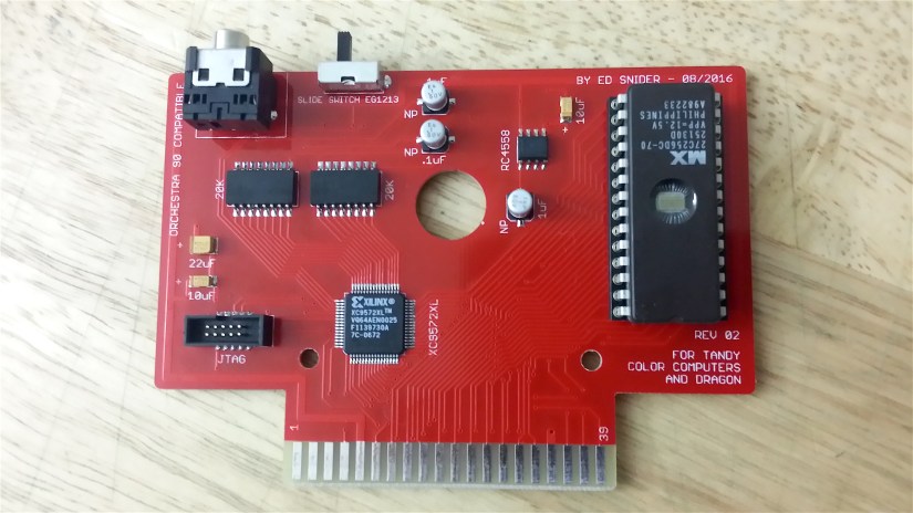
A “final” version of the external character ROM

After my first CPLD version of the MC6847 External ROM board, I decided to make a final, more refined version. I’ve made and distributed a number of these among members of the Color Computer group, and the boards look and work great.

20150709_181033.jpg
MC6847 External ROM – REV 03, top
20150709_181134
MC6847 External ROM – REV 03, bottom

This version uses the 64-pin version of the Xilinx 9572xl CPLD.  I’ve made use of all the available pins, some of them even just to ease laying out the board.  The design includes a 3.3v regulator to run the 9572, and a mini CPLD programming header.

A description of what the DIP switches do is as follows…

MC6847 External Character ROM – REV 03

DIP SWITCH SETTINGS

1 – Enable External ROM
2 – Inverse mode
3 – All Caps mode
4…7 – Bank selection 0…15 in binary

1) – Enable External ROM
Selects between MC6847’s internal ROM, and our external ROM.

2) – Inverse mode
Inverts the normal use of the INV line.  What was black on green is now green on black and vice versa.

3) – All Caps mode
To accommodate certain programs that are expecting inverted uppercase when the computer calls for a lowercase character, from the internal ROM, this mode does the following…

Decodes for any VDG calls for a lowercase character in external ROM (610h – 7A0h), and adds an offset to the address lines to the ROM chip.  Also triggers inverse mode.

The results will be like using the internal MC6847 ROM, but with the external character set.  Inverted uppercase in place of true lowercase characters.

4…7 – Bank Selection
Selects one of 16 character banks to use in binary

        Bank 0     Bank 1     Bank 2    Bank 3

        0 0 0 0    0 0 0 1    0 0 1 0    0 0 1 1

        – – – –    – – – –    – – – –    – – – –

Switch  4 5 6 7    4 5 6 7    4 5 6 7    4 5 6 7    etc….

20150823_102007
REV03 board, installed, closeup
20150823_101942
REV03 board, installed

Here are some screenshots of some alternate character sets and the different mode settings being displayed by a CoCo2 using the board.  This CoCo 2 is equipped with one of my composite boards including the B&W switch.  This is being used on the B&W screens.


CoCo VGA

The COCOVGA project provides VGA output for 6847 based systems. This is a collaborative project with Brendan Donahe.

This first iteration of the board operates in tandem with the MC6847. The VDG operates normally, and provides it’s usual video output to existing RF boxes and composite display options that are part of the system.

An Altera Cyclone IV FPGA monitors the buses and control signals of the MC6847 through level shifting ICs, and generates VGA video at the correct scan rate.

Though this version requires a 6847 IC to be present, we will be extending the design to fully replace the VDG in the future. We are proceeding with the “bus monitoring” version now in order to make a working VGA option available to users as soon as possible.

NTSC composite color artifacts are supported for the high resolution modes for programs that depend on them (most games on the CoCo1 and 2 for example).

At this point in the project, we have functioning development prototype boards, and working FPGA code (aside from a few issues that need to be worked out).

Design of production boards for some machines is already underway while the FPGA code is being developed further.

The first boards will be designed to fit early American CoCo2 motherboards, to be followed by boards specifically designed to fit other systems.

Here are some pictures of the prototype board and of our initial output. There is a lot of code development yet to be done, but we’re off to a great start.

20151013_095948
Prototype development board, with test points
MC6847 FPGA VGA DEV BOARD 062315
Board view in Eagle (prototype)
20151009_220616
Initial output, alphanumeric screen (prototype)

Video showing simulated early NTSC artifacts (prototype board)

Update 2017

We have come a long way since the initial prototype you see above on this page.
Since then I’ve designed our first production board that we are now on the verge of releasing for early American motherboard CoCo2’s (vertical RF modulator).

20160719_182542.jpg

20160719_182606

All of the standard 6847 video modes are supported, as well as a couple of new ones. In addition to the new video modes, all modes also have color palettes that can be set by the user. Color artifacts for the CoCo’s PMODE4 screen are simulated in several different selectable formats, and those artifact colors can be set by palette register as well if desired.

One of the new modes is VG6, a 128×96, 16-color mode. This mode gives 6847 machines some much improved graphics, especially considering that we can use whatever 16 colors we wish to on a screen. We can map any color from our output palette of 512 colors to a screen color via register settings.

Here are some early screen shots using VG6 with adaptive palettes.

Dragon
Flowers
Swirl
Picard2
MyPic

Lotus
Various 16-color images in VG6 mode displaying on the COCOVGA (CoCo2)

Another new mode implemented on our first model for release is a new Alphanumerics mode. This new mode is a 64×32 column text mode which rivals, and which I think actually outdoes the 80 column mode on the CoCo3. It can actually display more characters than an 80×24 screen, and is also in output in clean, clear VGA.

Here is a video of Brendan demonstrating the new mode…

As we moved closer to actually producing and distributing some of these VGA solutions to interested parties, it became clear that we needed to work on the rest of an installation package. A good way was needed to get the VGA generated by the video board through the CoCo’s case. Also, another feature Brendan and I wanted to add to the system was some simple manual controls for changing some of the video settings.

The solution I came up with is a small output board, with a mini-din connector and two pushbuttons. Dubbed ‘Button boards’, these mount to the CoCo top shell and plug into the VGA board via ribbon cable.

I wanted to make the installation as easy to do cleanly as possible, so I went with a mini-din connector, reasoning that round holes would be easier to do for most people (including me). This does require making a special VGA cable, but the system has worked very well so far.

20171011_181019.jpg
CoCoVGA ‘button boards’

Brendan requested a hardware debounce on the switches, so that’s the extra circuitry you see on the boards.

Here are some pics of a button board installed…

20170903_123905.jpg

20170903_123949
Button board installed in CoCo2 top shell

Update: October 2017

As of our initial release which occurred at the 2017 Tandy Assembly, Brendan and I are providing these to interested parties as we have boards available.  Development is continuing, with other versions to fit the many form factors needed for the different motherboards out there are being designed, as well as pursuit of various improvements/enhancements we have thought of to add to the system.

See much more about the COCOVGA at the official site

CoCo PSG

After working on the MC-10 Supercart, which adds memory and a YM2149 sound chip to the MC10, I thought it would be really cool to do something similar for the 6809 Color Computers.

The YM2149 is a programmable sound chip by Yamaha, based on the General Instruments AY-3-8910. The GI AY-3-8910 and it’s variants, including the YM2149 were used in a variety of early microcomputers and video games, and they are ideally suited for use with 8-bit systems.

There is a large amount of music available that is compatible with these chips that has been composed on several systems which is adaptable for play on a CoCo cart like this. This gives us the possibility of a large library of music to play, as well possibly being of use with tracker style composition software written for the CoCo. Not to mention sound effects for games and other programs.

Major components

Along with a YM2149, we’ll need some associated circuitry in the form of a transistor amp output circuit, and an oscillator. To provide some additional resources for the CoCo when using the chip, and to store software for the cart, we’ll also add 512K of FLASH, and 512K of SRAM.

Using chips of this size (512K each) is handy as far as handling memory banking using 8-bit registers, and will provide us quite a bit of storage and RAM on a CoCo for our chiptunes software to use.

Then we just need a CPLD to handle the needed logic to tie it all together and provide the registers. A 5V tolerant XC9572XL in the 64 pin QFP package should do nicely.

CoCo PSG.jpg
Eagle .brd view of the CoCo PSG prototype

Since the YM2149 chip also includes two 8-bit bidirectional I/O ports in addition to the sound control registers, we may as well use them to add a couple of ports. These are wired to make them useable with Atari style joysticks and Sega Genesis game pads. You could also use them for other things of course, they’d just have to be programmed for.

The oscillator chosen to drive the YM2149 is 2MHz, the same frequency that was used in the Atari ST. The *SEL pin on the YM2149 is connected to the CPLD, and the clock rate can be divided by 2 (to 1MHz) under software control if desired.

Memory banking

The 1MB of combined FLASH and SRAM is bankable to two memory locations in 8K banks. The two 8K memory segments are located in cartridge ROM space as follows;

Bank 0, $C000-$DFFF
Bank 1, $E000-$FEFF

Both types of memory may be mapped to any of the two banks using two 8-bit registers in the CPLD.

There is a third 8-bit register (the PSG control register) which has features for enabling writes to the memory chips, driving *SEL lines for reading gamepads, selecting PSG clock frequency, etc…

PCB Top.jpg

PCB Bottom.jpg
CoCo PSG prototype PCB

Sound output

The YM2149 outputs 3 channels of sound. On this initial version, the three channels are mixed into a single channel and output at the small stereo jack on the board (both channels the same). I believe this is how most early systems handled AY style chips, though I know some would use channels A+B for one and B+C for another output channel for “stereo”.

Other possibilities, such as selectable channel mixing could be supported with the use of analog switches, but for now we’ll keep it simple. A revised version will include output on the cart port’s SND line for playing without external speakers as well.

20161204_144551.jpg

20161204_144606
Assembled CoCo PSG, top and bottom


UPDATE – 10/25/17

It’s been quite some time since I wrote the above about the CoCo PSG at the start of this project.

I went through a few board revisions during development to arrive at the current board (REV 04), which is in it’s final form (I believe) at this point. Several changes have been made, including a new audio output circuit based on an op-amp rather than transistor. Sound is also fed back through the cart port on the CoCo’s sound-in line as well as being available at the external jack.

CoCo PSG - REV 04 Layout.jpg

Other changes include banking the additional memory at two 8K banks instead of the original format.

I built a number of these to distribute to developers and other interested people that might want to work with them and perhaps write some software to take better advantage of them.

20170716_194857.jpg

20170531_200224
First release, REV 03

Also, John Strong from the CoCo group designed some very nice 3d printed cases for these, making for a nicely finished sound cart.

20170907_153250.jpg

20170907_153355.jpg
Cases!

Here is a video of a chiptune playing on the cart with the signal being displayed on an oscilloscope. 🙂

Audio playing from the PSG, with actual oscilloscope trace

Here is a link to the CoCo PSG Users Manual, with some programming information.

MCX-128

The MCX-128 is a memory expansion for Radio Shack’s MC-10 microcomputer
designed by Darren Atkinson. Plugging into the expansion port at the rear of
the computer, it adds a 128k static RAM chip, and a ROM socket that will
accommodate 27128, 27256, 27512, or compatible ROM/EPROMs, and
some logic to tie it all together.

20150314_215816
MCX-128

The ROM holds the operating system MCX BASIC, also by Darren.
The memory upgrade along with MCX BASIC allow the MC-10 to use a
client/server package called Emcee Server.

20150314_220146
MCX-128 in an MC-10

I produced a small run of these recently (30) with Darren’s permission. If you see one with a white solder mask, it’s one I produced.

6oyc9wf37fyejzyzg
Several MCX-128 Units

COCODAC-16

Not too long ago, it came to my attention that Pere Serrat had modified the ROM for the Orchestra 90cc to make it work with Dragon computers. This inspired me to design and build a compatible board that would run the original software, and be useable in both Dragons and Color Computers.

Orchestra-90_CC
Original Orchestra90-CC

The first thing I had to do was figure out how the original worked. I had an original cart in my possession, but didn’t want to ruin the label by cracking it open. Luckily, the manual for the original is out there in .pdf form, and includes a schematic. Here it is…

Orchestra-90 Schematic.jpg
Schematic for the Orch 90

As you can see from the schematic, there isn’t a lot of circuitry there. Some TTL logic for address decoding, a couple of data latches, a couple of resistor DACs, a ROM chip, and some audio output circuitry.

The system uses two 8-bit DACs driven by the latches (using data bus signals) to create the sound waves. It’s stereo, one DAC per channel. The decoding logic decodes for two addresses used to write the latches. The ROM contains the software, and is tied to the Color Computer bus in the usual fashion, using !CTS as the output enable line, with Q and !CART tied together to autostart the program.

The output circuitry (after the DACs) consists of a handful of capacitors, and an op-amp circuit that feeds both channels mixed together back through the SND line so that the sound can be included with the computer’s built in sound or RF output.

I decided to use modern surface mount components (mostly) for size considerations, and because I just like working with them more than through hole now.

I figured a 5v tolerant CPLD could be used to replace all the logic on the board, and selected the Xilinx XC9572XL in the VQFP-64 package. Bourns SMT resistor packages would do nicely for the DACs. And the original op-amp is still manufactured and available in a nice little SMT package, so why not just stick with it.

After a first prototype, which worked fine, I made a few minor changes to the capacitors I was using. The result was the REV 02 board, which is the final version.

REV02 Eagle View.jpg
REV02 Eagle board view

I used a 32K ROM, to hold software for both Color Computers and Dragons.   The platform can be selected using the slide switch beside the stereo jack.  Below are pictures of the assembled board, and pictures of it in a case.

20160818_231657

20160818_231713
Assembled PCB, top and bottom


20160801_220809

20160801_220822
In a case


First test


In a Tano Dragon

And here are some links to line-in recordings of a couple of Orchestra 90 tunes using the REV02 boards. Headphones or good speakers recommended to hear everything.

Jump

Hideaway